An I-beam is a structural steel section with an I-shaped cross-section: two parallel flanges connected by a single vertical web. That is the definition in one line. Everything else in a working description — depth, flange width, web and flange thickness, grade, length and straightness — exists because the shape alone does not tell a mill, a detailer or a welder what to do with it.
Most people searching for an I-beam description need one of four things: a plain definition for a drawing note or a submittal, a size designation they can actually order, a way to tell a hot-rolled beam from a welded one, or a short checklist of details to verify before the steel is accepted. The sections below take those in order and keep the numbers concrete.
The short answer: describe an I-beam with six items — depth, flange width, web thickness, flange thickness, length and steel grade. "IPE 300, S355JR, 12 m, EN 10365" is a description. "200 by 100 I-beam" is a nickname.
What Is an I-Beam? Definition and Anatomy
An I-beam is symmetric about both axes and concentrates material in the flanges, which is exactly where bending stress is highest. Because of that distribution, an I-beam carries several times the bending load of a solid rectangular bar of the same weight and depth — and that single fact explains why the profile survives in almost every steel structure ever built.
Six measurements define the section. They appear in every mill catalogue and in every description worth writing.
| Element | Common symbol | What it controls |
|---|---|---|
| Depth | d or h | Overall height of the section; drives bending capacity and the headroom left in a floor build-up. |
| Flange width | bf or b | Width of the top and bottom plates; drives lateral stability and how much room a bolted or welded connection has. |
| Web thickness | tw | A thin web is light and efficient, but shear and local buckling start to govern the design. |
| Flange thickness | tf | Governs local bending, bolt bearing and the depth available for any weld preparation. |
| Root radius | r | The fillet where web meets flange; sets the clear distance for bolts and the space a welding torch can reach. |
| Length | L | Ordered mill lengths are quoted in metres or feet; cutting, coping and drilling change the delivered length, not the section. |
I-Beam, H-Beam and Wide-Flange: Same Family, Different Proportions
"I-beam" and "H-beam" are not two different products. They describe the same family of shapes; the name usually tells you how wide the flanges are relative to the depth. A deep section with narrow flanges looks like a capital I, and widening the flanges toward the depth turns the same profile into something that looks like a capital H. Codes and mill catalogues gave the two extremes different names, and that is where most of the confusion on drawings comes from.
Three things change as flanges widen: the lateral stiffness of the beam, the mass for a given depth, and the connection details that will physically fit.
| Name | Where it comes from | Flange style | Typical use |
|---|---|---|---|
| I-beam (generic) | General industry, older US "S" shapes | Narrow flanges, sometimes tapered | Retrofits, small monorails, light framing |
| Wide-flange W shape | AISC / ASTM A6, North America | Parallel flanges, wide relative to depth | Building frames, columns, floor beams |
| IPE | EN 10365, Euronorm | Parallel flanges, narrow and light | General steelwork, machinery frames |
| HEA / HEB / HEM | Euronorm | Wide flanges, increasing weight and wall thickness | Columns, heavy frames, crane structures |
| HW / HM / HN | GB/T 11263, China | HW wide, HM medium, HN narrow | Steelwork for domestic Asian and export projects |
| H-shape (JIS) | Japan | Parallel flanges, similar to wide-flange | Frames, supports, general fabrication |
How to Read an I-Beam Size Designation
A designation is a shape code plus one or two numbers, and it is never the whole specification. W12x26 means a W-shape nominally 12 inches deep weighing 26 pounds per foot. IPE 300 means a parallel-flange I-profile 300 mm deep. HEB 200 means a heavy wide-flange H-section 200 mm deep. In every case the nominal number is close to — but not exactly — the real dimension, and it is the mass, not the depth, that you pay for.
| Designation | Depth | Flange width | Web thickness | Flange thickness | Mass |
|---|---|---|---|---|---|
| W12x26 (AISC) | 310 mm | 165 mm | 5.8 mm | 9.7 mm | 38.7 kg/m |
| W12x40 | 303 mm | 203 mm | 7.5 mm | 13.1 mm | 59.5 kg/m |
| IPE 200 | 200 mm | 100 mm | 5.6 mm | 8.5 mm | 22.4 kg/m |
| IPE 300 | 300 mm | 150 mm | 7.1 mm | 10.7 mm | 42.2 kg/m |
| HEB 200 | 200 mm | 200 mm | 9.0 mm | 15.0 mm | 61.3 kg/m |
| HN 400x200 | 400 mm | 200 mm | 8.0 mm | 13.0 mm | 66.0 kg/m |
Two rules prevent most ordering mistakes. First, imperial designations quote a nominal depth and the real mass per foot: the actual depth across the W12 series alone spreads over roughly 45 mm, from about 303 mm to about 348 mm. Second, metric designations give the depth exactly — IPE 300 is 300 mm deep — but the wall thicknesses still have to be looked up, and two profiles of the same depth can differ by nearly three times in weight.
Standard Lengths, Steel Grades and Tolerances
An order that says only "I-beam, 12 m" is buying a shape of unknown strength, unknown straightness and unknown paperwork. Length, grade and tolerance should be specified together, because that is how a mill reads the request.
Mills roll to 6 m, 12 m and occasionally 15 to 18 m, while imperial markets quote 20 ft to 40 ft. Twelve metres is the usual compromise between fewer splices and road transport limits, and it is the length most export shipments are planned around.
Four grades appear on most drawings:
- ASTM A36 — 250 MPa yield, easy to weld, common in North America for light framing and general fabrication.
- ASTM A992 or A572 Gr. 50 — 345 MPa yield; A992 is the standard W-shape grade for building frames.
- EN 10025-2 S355JR or S355J2 — 355 MPa yield, with the JR and J2 suffixes indicating Charpy impact toughness for colder service.
- GB/T 1591 Q355B — the common Chinese grade, frequently dual-certified to EN or ASTM on export projects.
Three tolerances cause most of the arguments on site: camber (the vertical bow), sweep (the horizontal bow) and twist. A typical wide-flange limit is 1/8 in per 10 ft of length, or roughly 0.1 percent, which means a 12 m beam may legally bow around 12 mm and still pass. Flange out-of-square and length tolerance are separate limits again. If the beam has to sit flat on a base plate or line up with a splice, put the straightness class on the order rather than discovering it in the shop.
Hot-Rolled or Welded? The Description Tells You
A description that says "hot-rolled W-shape", "IPE" or "HEB" means the beam came out of a mill as a single piece. A description that says "welded plate girder", "built-up beam" or "fabricated H-section" means the flanges and the web were cut from plate and joined by welding. Welded fabrication is how you get non-standard depths, very thick flanges, and single pieces longer or heavier than any rolling programme allows.
Welded beams shift the quality control into the shop. The web has to be set square to the flanges before tacking, heat input has to be controlled so thin webs do not bow, and the joint should be welded flat, with the beam turned so the weld sits horizontal. On long web-to-flange joints, that turning and travelling weld is normally made with a submerged arc head carried on a carriage. Shops that do this at volume move toward automated welding for large metal structures not only for speed, but because a manual weld along a 12 m joint is almost impossible to repeat.
Column and boom welding systems hold the torch head at a fixed angle while the carriage runs the length of the beam, which is what makes a consistent bead and a predictable heat input possible in the first place.
 SAW Column and Boom Welding System for Long SeamsA submerged arc welding column and boom that positions the torch precisely for consistent beads on thick plates and long longitudinal seams.View Product →
Positioning: The Step Most Descriptions Leave Out
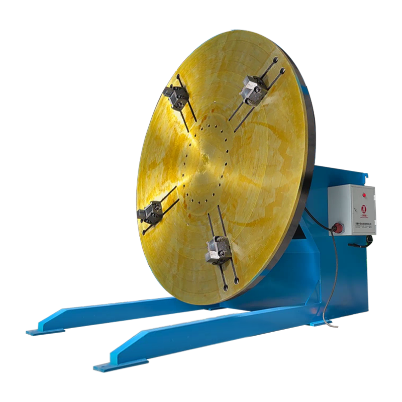
Welding a beam in place works for short pieces. For anything heavy, or anything that needs a weld made overhead, the weldment should be turned so the joint is flat and the operator is not fighting gravity. That is a positioning problem rather than a welding problem, and it is normally solved with a positioner or a turning device rated for the load and for the offset centre of gravity.
Two numbers decide the machine: the mass of the weldment, and how far its centre of gravity sits from the centre of the table or the rollers. A positioner rated for 5 t holding a 5 t weldment whose centre of gravity sits 800 mm off-centre sees an overturning moment that has nothing to do with the load rating alone. Rotation torque, clamping method and the flatness of the mounting surface all have to be checked together, ideally before the first weld is laid.
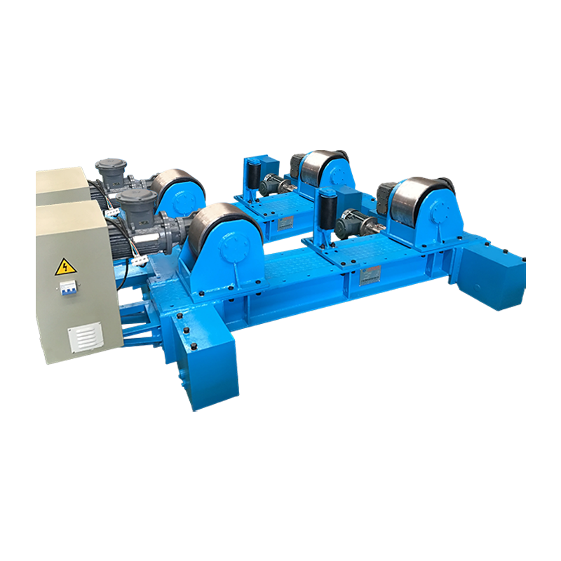
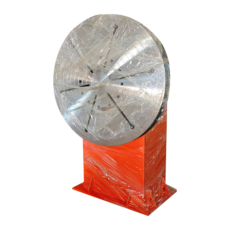 Double Column Welding Positioners for Large Heavy FabricationsTwo coordinated supports with VFD rotation and constant-speed lifting for large, heavy or irregular workpieces up to 10–200 tons.View Product →
Where I-Beams Are Used
I-beams are chosen wherever a structure has to carry bending across a span with the least possible steel, which covers most of the built environment.
- Building frames — floor beams, columns and mezzanine decks
- Bridges — stringers, cross bracing and temporary works
- Crane runway beams, monorail tracks and lifting frames
- Machine bases, skids and industrial equipment frames
- Trailers, chassis and transport structures
- Wind turbine internals — nacelle frames, tower platforms and internal supports
- Conveyor gantries, racking and storage structures
Wind work shows how the two halves of a fabrication shop meet. The tower is cylindrical and turns under a stationary torch; the internal frames and platforms are beams and are welded flat. Shops serving that industry usually need both a beam welding setup and a rotator, because round sections are welded with the workpiece rotating while the torch stays still.
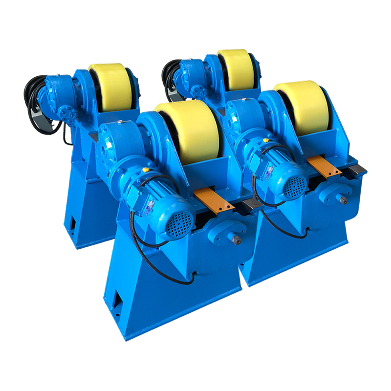
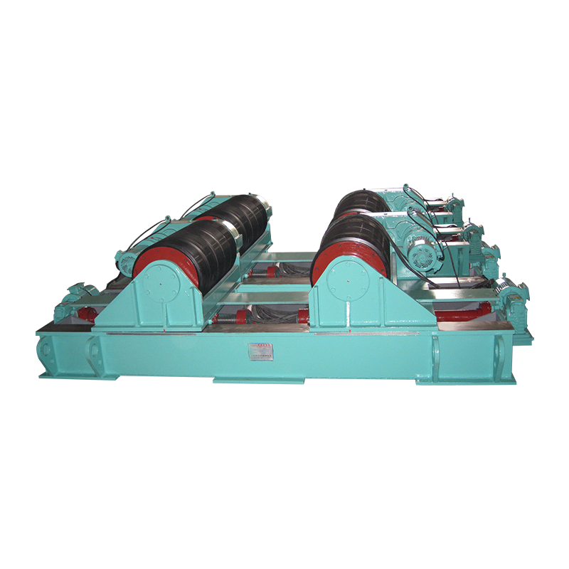
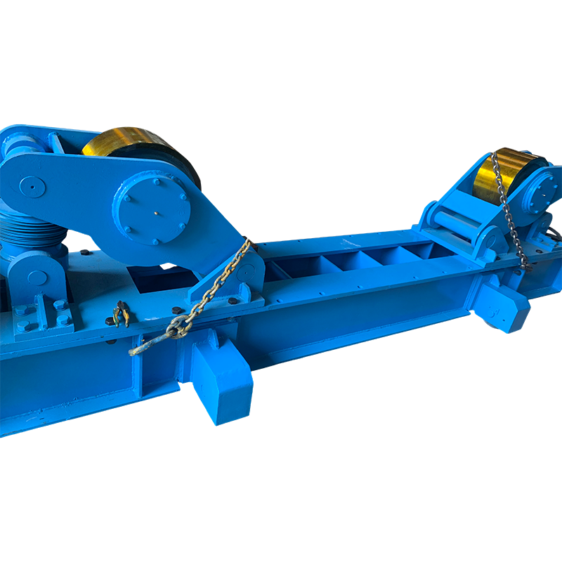 100T Fit Up Welding Rotator with Manual Orbital MovementA 100-ton fit-up rotator with manual orbital travel and adjustable rollers for smooth rotation of cylindrical workpieces during circumferential and longitudinal seam welding.View Product →
What to Specify When You Order an I-Beam
An order that carries these seven items rarely comes back with a question.
| Item | Why it matters | What to write |
|---|---|---|
| Designation and standard | Fixes the geometry of the section | W12x40 to ASTM A6; HEB 200 to EN 10365 |
| Steel grade and impact class | Fixes strength and toughness | A992; S355J2; Q355B |
| Length and cutting | Affects transport, handling and splices | 12 m mill lengths, or cut to drawing |
| Mill certification | Traceability for the project file | EN 10204 3.1 certificate or mill test report |
| Straightness and camber | Drives fit-up quality on site | Standard, or 0.1 percent of length if alignment is critical |
| Surface condition | Decides coating and weld preparation | As-rolled, blast cleaned to Sa 2.5, or primed |
| Fabrication done at source | Decides what your own shop must do | Holes, copes and camber rolled in, or left to the fabricator |
Frequently Asked Questions About I-Beams
Is an I-beam the same as an H-beam?
For practical purposes, yes — both names describe an I-shaped section. The distinction is proportion: traditional I-beam shapes have narrow, sometimes tapered flanges, while wide-flange and H-section shapes have parallel flanges that are wide relative to the depth. The difference shows up in lateral stability, connection space and weight.
What does W12x26 mean?
It is a W-shape nominally 12 inches deep with a mass of 26 pounds per foot, about 38.7 kg per metre. The 12 is nominal only, since the real depth of a W12 section varies across the series, so section properties should always be taken from the catalogue rather than from the name.
Which way up is an I-beam strongest?
Standing up, with the flanges horizontal. Bending capacity rises steeply with depth, so the same beam laid on its side loses most of its strong-axis strength and relies on much smaller weak-axis properties. When a beam is used as a column, it has to be checked for buckling in both directions instead.
Can an I-beam be welded?
Yes, provided the weld is made to a qualified procedure. Two points matter more than the welding itself: the carbon equivalent of the grade, which decides whether preheat is needed for thick flanges, and the heat input, which decides how much the web will bow. Thin webs and long joints are where distortion becomes expensive.
What is the difference between IPE and HEB?
Both are parallel-flange European sections, but HEB has much wider flanges and thicker walls for the same depth: IPE 300 weighs 42.2 kg/m, while HEB 300 weighs 117 kg/m. IPE suits beams where bending strength matters and lateral support is available; HEB suits members that also act as columns, lifting points or heavily loaded supports.
If you remember one thing, remember that an I-beam description is a set of numbers rather than a name. Depth, flange width, web thickness, flange thickness, length and grade — plus a clear statement of whether the beam is hot-rolled in one piece or welded from plate. Put those items on the drawing and on the purchase order, and the questions get answered at the desk instead of on the shop floor.